Dynamic Resistance Measurement and OLTC Analysis

Analysis of the OLTC condition used to be a complicated and expensive proses. Since the OLTCs are placed inside the transformer tank, it was necessary to disconnect the power transformer from the network, open it and remove the transformer oil. Once these actions have been performed, it was necessary to visually check mechanical condition of the OLTC. This procedure was difficult and time consuming, and the results were not always reliable.
Ther is big amount of varierty among thr OLTCs in today's market. they differ in the number of tap positions, number and type of transition resistors, methods of switching, etc. Up to very recently, only the static behavior of the contact resistances has been taken into consideration in maintenance testing and diagnostics of power transformers. The DVtest (DRM) method can successfully diagnose and analyze the state of all OLTC types.
Ther is big amount of varierty among thr OLTCs in today's market. they differ in the number of tap positions, number and type of transition resistors, methods of switching, etc. Up to very recently, only the static behavior of the contact resistances has been taken into consideration in maintenance testing and diagnostics of power transformers. The DVtest (DRM) method can successfully diagnose and analyze the state of all OLTC types.
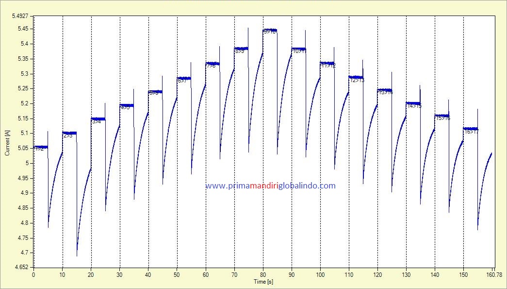
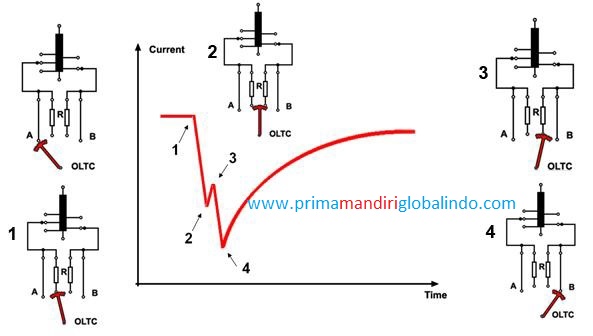
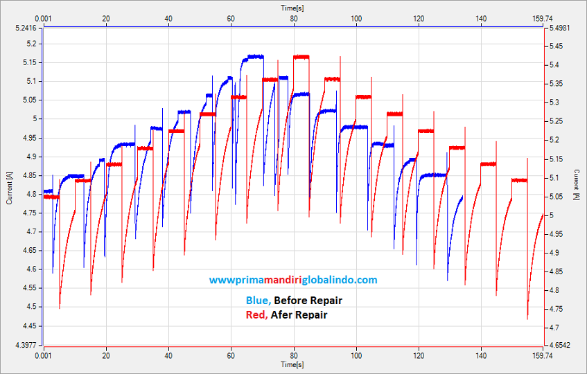
The DVtest is actually the measurement of the test current change during the transition. The current represent the change of the resistance in the circuit during the change of the tap position. The current is an inverse to the total re sistance of the circuit (winding resistance + OLTC contacts resistance). The results are obtained using the RMO-T or TWA series devices together with DV-Win PC software.
An example of an OLTC in the figure below. It consists of the tap selector part and the diverter switch part. This OLTC type has two transition resistors in the diverter. Switching problems of the diverter switch can be detected by analyzing several key features of the DVtest graph which is shown.


